Vehicle-Mounted UAS Automated Flight Testing Rig
Project Overview
This project involved designing and validating a vehicle-mounted propulsion testing system for unmanned aerial systems, sponsored by Firestorm Labs. The goal was to provide a cost-effective alternative to full-scale wind tunnel testing by mounting a UAS propulsion test article to the roof of a vehicle and using highway-speed driving to generate realistic airflow conditions.
The system was designed to safely secure the test article, withstand high-speed aerodynamic loading, and collect thrust, aerodynamic force, airspeed, and temperature data during test runs. My primary contributions focused on CAD design, structural load analysis, FEA validation, sensor integration, and data acquisition.
This work was presented to both an academic engineering review panel and a Firestorm Labs company panel as part of the final design validation and handoff process.
🛠️ Technical Implementation & Software Architecture
I led the CAD design of the full test structure, defining the overall architecture, load path, support geometry, sensor placement, and wiring integration. The final design used a roof-mounted support structure with a streamlined stand to reduce flow disturbance while positioning the propulsion system in cleaner airflow above the vehicle roof.
Using CFD results from the team’s aerodynamic analysis, I independently conducted the statics analysis for the entire structure to determine maximum operating loads at critical design points. These calculated loads were then used to validate the stand, mounting interfaces, and load-cell stack under conservative aerodynamic and inertial conditions.
I also performed structural FEA to verify that the printed components could withstand the expected loading while maintaining the stiffness needed for accurate force measurement. For instrumentation, I selected and integrated a six-axis load cell, pitot-static airspeed sensing, and thermocouples, then developed data collection and processing code to convert raw sensor outputs into usable performance metrics.
Key methods and components included:
- Full CAD assembly modeling
- Structural statics and load-path analysis
- Structural FEA validation
- Six-axis load cell integration
- Pitot-static and thermocouple instrumentation
- Sensor wiring and data acquisition setup
- Real-time force and telemetry processing
📊 Experimental Validation & Results
The design was validated through structural analysis, FEA, physical load testing, and system-level instrumentation planning. The statics analysis established the maximum expected loads at critical points in the structure, and the final design was sized using an added factor of safety beyond those calculated operating loads. FEA was then used to confirm that the stand and mounting interfaces remained below material yield limits under these conservative design conditions.
The final system used a vertically stacked force-measurement layout, allowing propulsion and aerodynamic loads to pass through a defined load path into the six-axis load cell. This enabled the system to measure thrust, drag, lift, crosswind loading, and moments during testing.
As an additional honors project, I independently completed a comparative engineering study evaluating the vehicle-mounted system against a traditional full-scale wind tunnel. The study compared both approaches across cost, accuracy, repeatability, and safety, concluding that while wind tunnels offer superior data quality, the vehicle-mounted system was the more practical near-term solution for Firestorm Labs.
Final CAD Assembly
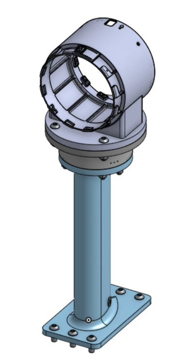
Final Assembly
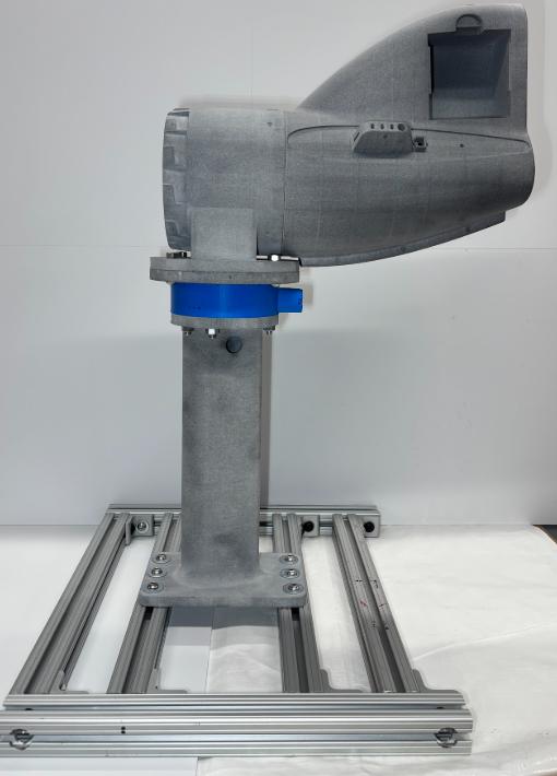
Code & Design Files
The data acquisition code, detailed engineering drawings, calculations, and proprietary design files for this sponsored project are not publicly shown.